System Overview
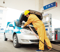
CNG refers to compressed natural gas,which means the low pressure gas is pressurized to 25 MPa and becomes a high-pressure natural gas.
The liquefied natural gas (LNG) is transported to the filling station which is then purified, pressurized and dehydrated. It will then be passed through the sequence control panel and fed into the gas storage system where it is measured and used by external users through the filling machine.

Process Flow Diagram of the CNG Regulator Station with Gas Storage Device
Major Component
-
Natural gas regulator metering system
-
Natural gas purification system
-
Natural gas compression system
-
Natural gas storage system
-
CNG filling system
-
Control system
Technical Features
-
LNG fueling stations will not only fuel LNG vehicles but with the installation of a simple high pressure pump and vaporizer, they can also generate high quality CNG gas in the same station for different applications.
-
CNG generated from LNG is called LCNG. Both LNG and LCNG can be delivered at the same single station.
-
A LNG/LCNG fueling station is more flexible than a single functional NG fueling station since it provides service to short fueling range vehicles and also long fueling range LNG vehicles.
-
When a natural gas vehicle (NGV) fueling station is planned, it will typically be both a LNG and LCNG combined station and is depicted in the following diagram.
The Filling Stations of Compressed Natural Gas (CNG)
Applications
The CNG filling station is primarily used for refilling cars which use the natural gas as fuel. This technology has been successfully applied to the Huoqiu, Anhui LNG filling station and more such stations throughout China.
The Natural Gas Vehicle (NGV) Fueling Station
Liquefied Natural Gas (LNG)
LNG is natural gas extracted and purified from gas fields, and then pressurized to liquefied natural gas at temperatures below -162°C.
LNG is colorless, odorless, non-toxic and non-corrosive, and is about 1/600 the volume of the same amount of gaseous natural gas. Its weight is approximate about 45% that of water.
LNG Gasification Station Process Flow Diagram
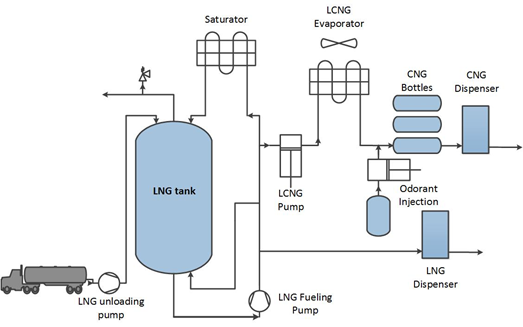
LNG/L-CNG Fueling Station
LNG/L-CNG filling device is consisted of LNG storage tank, immersed pump, fluid adding machine, cryogenic column piston pump and skid-mounted high pressure vaporized skid, boil off gas (BOG) vaporizer, escape air gas (EAG) vaporizer, BOG buffer tank, BOG compressor, sequence control panel, storage cylinder set, gas dispenser, pipeline and valves. The station control system includes programmable logic controller (PLC) control system, gas alarm system, instrument air system and BOG collecting control system.
L-CNG Fueling Station Components
In L-CNG fueling stations, the major equipments are the LNG storage tank, LNG truck unloading system, LNG saturation heater, high pressure positive displacement pumps, high pressure LNG vaporizers, CNG storage bottle bundle/priority controls, odorant injection, dispenser and control systems.
Application
This technology has been successfully applied to the Honggang city gas project, Jiugongshan city gas project and other projects in China.

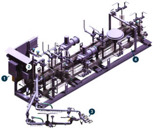
3D View of the LNG Unloading Skid
1. Local Control Panel; 2. Preset-Controller; 3. Loading Arm; 4. Mass Flow Meter
System Overview
Primary energy is combined by various conversion methods in the combined cooling, heating and power (CCHP) system, which can directly provide electricity to water chillers, heating systems, steam generators and other terminal energy services systems for users in an economical and efficient manner. The energy can be integrated and optimized with cold, heat and electricity production technologies.
Technical Features
-
The energy efficiency is up to 80%;
-
Clean energy and sustainable, without extra contamination;
-
System capacity is flexible with good economics.
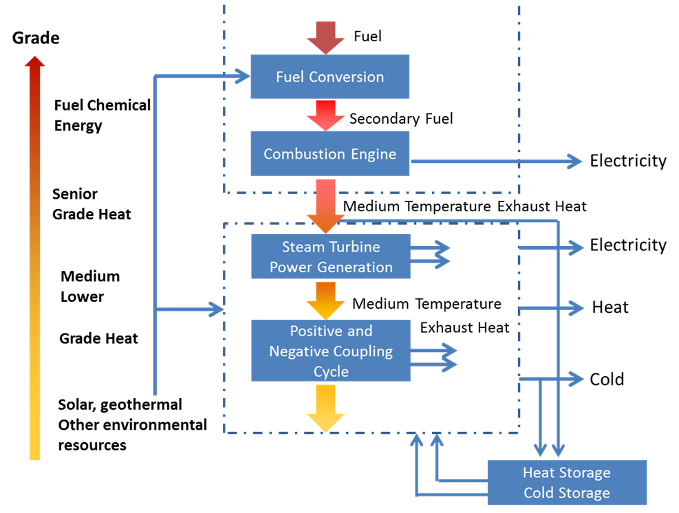
Flow Diagram of Energy Cascade Utilization
Application
As a result of China's electrical market reform and policies to promote combined cooling, heating and power (CCHP), SafBon has completed numerous distributed energy projects that can meet the increasing demand of various clients. These projects provide industrial parks, commercial buildings, and other industrial and commercial customers with comprehensive energy solutions via CCHP.
The CCHP station technology is applied in:
-
Hotels, hospitals and other building types;
-
Area types of natural gas distributed energy projects;
-
Biomass gas distributed energy projects;
-
Industrial waste gas distributed energy projects.
NG Regulator Station
SafBon’s natural gas (NG) regulator station can be divided into the boosting station and the reducing station with a carefully designed system device to boost and reduce the pressure of fuel gas in the pipes of the fuel gas network. It is a highly integrated system which incorporates clean filtering, boosting, reducing, metering, temperature control, leaking, alarming and data acquisition monitoring for fuel gas. It is used to condition and control the pressure, temperature, and flow of the natural gas while cleaning and filtering the stabilized fuel provided to customers and gas equipment which requires such fuel.

Pressure Reducing Valves Operational Schematic
Functional Specifications
The system shall be designed for the following requirements:
-
Supply of fuel gas (natural gas) to two gas turbines at sufficient flow, quality and pressure.
-
Separation of dust and fluid impurities from the fuel gas by the first filtering stage.
-
Measurement of flow rate and gas composition for calorific value calculations.
-
Preheating of the fuel gas to avoid the formation of condensates at the pressure reduction stage and in the transfer pipeline to gas turbines, in an indirect heater.
-
Reduction of pressure at the pressure regulating station.
-
Recording of the fuel gas consumption of each gas turbine by a turbine meter individually at each gas turbine.
-
Protection of the gas turbines by final filters.
-
Protection of the system from over pressure.
-
Monitoring for gas leakage.
Technical Features
The NG regulator station consists of the following thirteen main parts:
-
Unit 1 Emergency stop valve at the inlet to the gas system
-
Unit 2 Knock out drum and filter
-
Unit 3 Orifice meter
-
Unit 4 Gas pressure regulator station
-
Unit 5 Fuel gas compressors
-
Unit 6 Fuel gas heater
-
Unit 7 Outlet safety cut-off
-
Unit 8 Condensate collection and disposal system
-
Unit 9 Nitrogen purging system
-
Unit 10 Instrument control instructions
-
Unit 11 Relief piping system
-
Unit 12 Surface treatment and paint
-
Unit 13 Leakage detection and fire warning & control system

Centrifugal Compressor
Application
The NG regulator station technology is mainly applied in:
-
CCPP(Combined Cycle Power Plants);
-
Power plants that use nature gas as fuel;
-
The industries that use natural gas as fuel;
-
Gas fired boilers;
-
CCHP(combined cooling, heating and power systems);
-
City gas and natural gas transmission pipelines.
System Overview
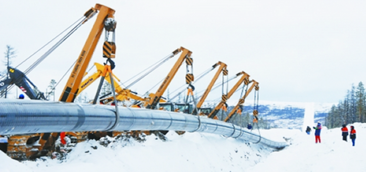
SafBon can provide the natural gas long-distance pipeline investment as well as the services of its construction and operation. In order to develop the natural gas long-distance pipeline and city gas pipeline network in both construction and operation, SafBon has improved its ability in carrying out the project construction from upstream to downstream industries.
Applications
-
The gas transmission lines from the neighboring cities.
-
The gas transmission lines from the oil and gas gathering station.
-
The gas transmission lines from the coal gas plant gas gathering station.
-
The gas transmission lines from artificial gas plants, coking plants, petrochemical plants.